Fritzing
Interface design & usability for the open-source PCB tool
From 2007 onward I was the interface designer and usability evangelist for Fritzing, the open-source application that lets designers, artists and makers move from a breadboard sketch to a finished, producible circuit board.
Fritzing is a software application that helps designers, artists and other makers
document, prototype and produce their own electronic circuit boards.
Where most electronic design software is difficult to use, expensive and aimed at engineers,
Fritzing is open source, free, and built to be genuinely easy and friendly,
especially for people new to electronics. From the end of 2007 onward I was the
interface designer and usability evangelist.
Throughout the design and development process we made a lot of paradigm shifts, always in favour of the user. Designing printed circuit boards is a complex system leaning on many dependencies, so usability wasn’t a nice-to-have: it is vital to the project, since it determines whether a user with limited knowledge of electronics succeeds or not.
The premise of Fritzing is that sketching in electronics begins on a breadboard.
Physical prototyping tools like Arduino have come a long way
and already let non-engineers turn ideas into working interactive sketches
quickly.
However the biggest issue with the prototypes in this stage is that they stay raw and fragile.
This is where Fritzing comes in: it lets the designer move to the next stage and
turn an individual circuit into a finished PCB in the shape they want, robust
enough for a permanent installation or even small-batch production.
Over the project we moved the application itself from a Java/Eclipse environment
to C++ with Qt, and from an entry tool that depended on Eagle to a standalone
application producing its own Gerber files.
The images here show some of the design work and the process we went through as a team.
Drag & drop sketch
An early animated sketch of dragging a part from the parts bin onto the canvas, made to study the interaction’s affordances and preclusions.
The wider development-cycle thinking behind where Fritzing fits in a maker’s workflow grew into a separate teaching piece, The Development Cycle.
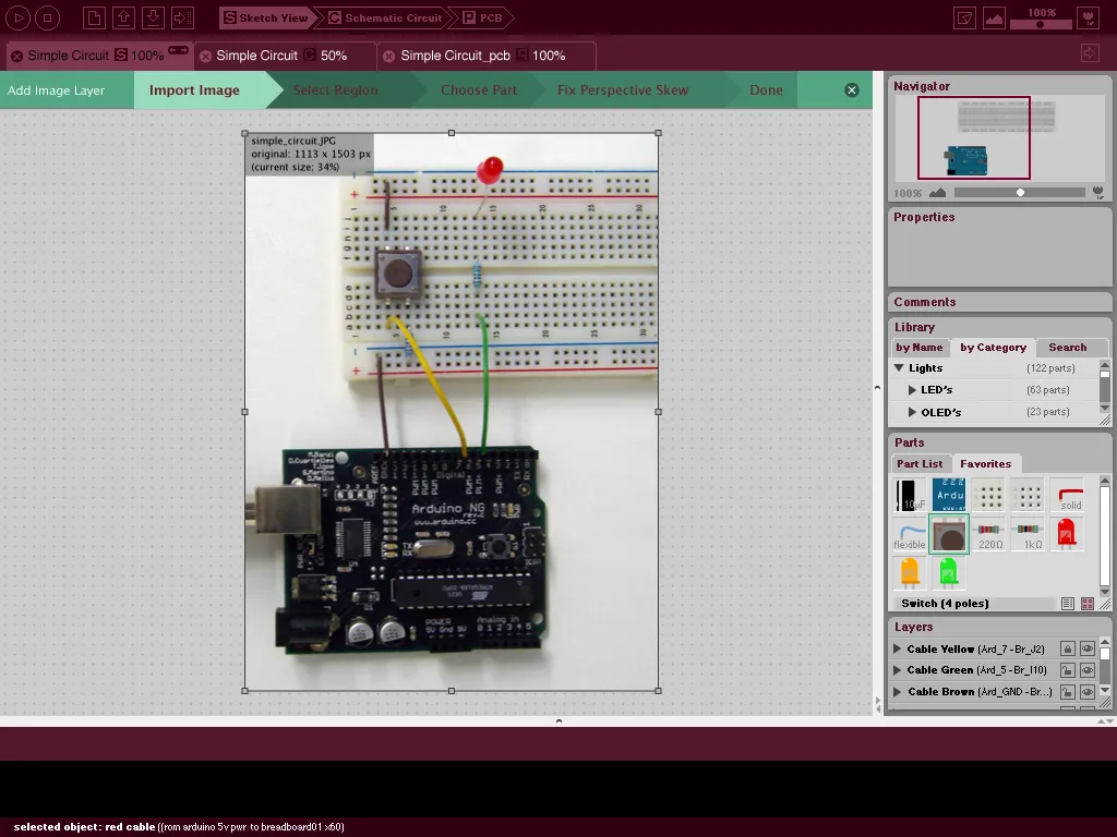
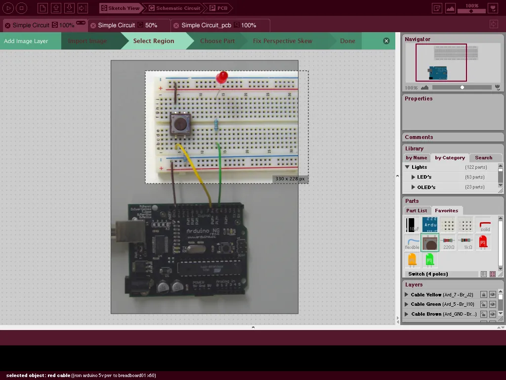
Initial pitch
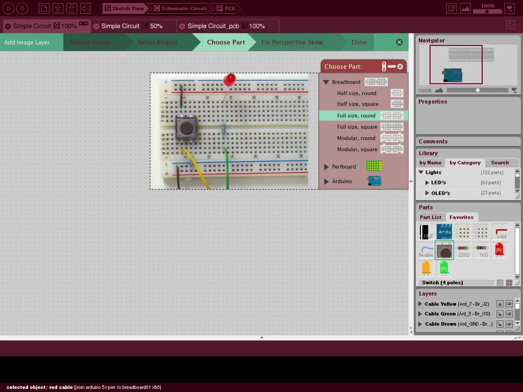
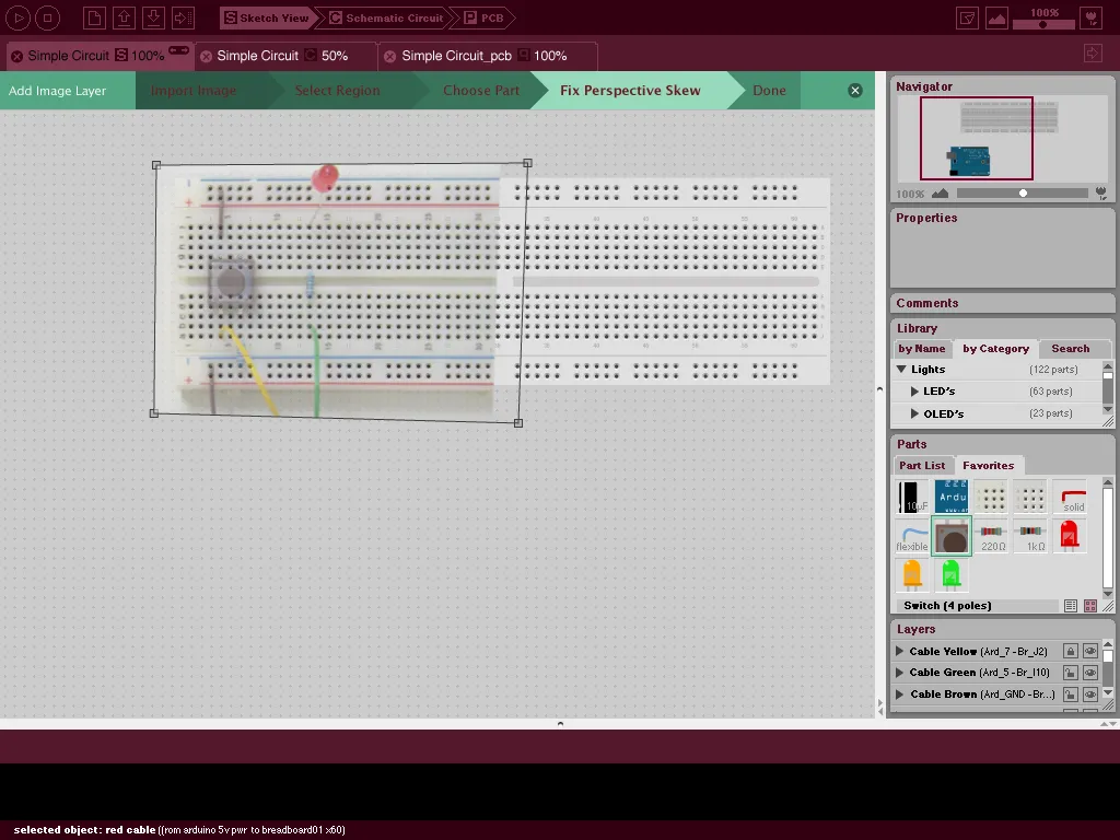
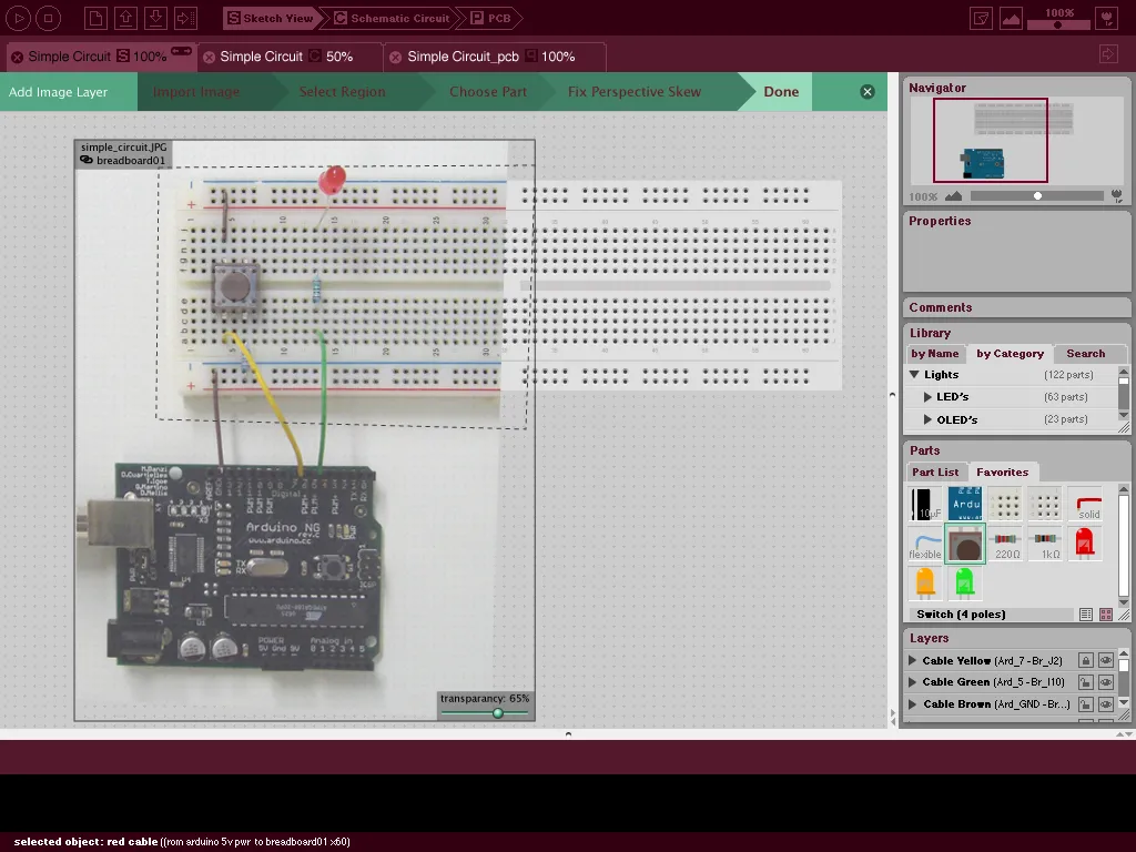
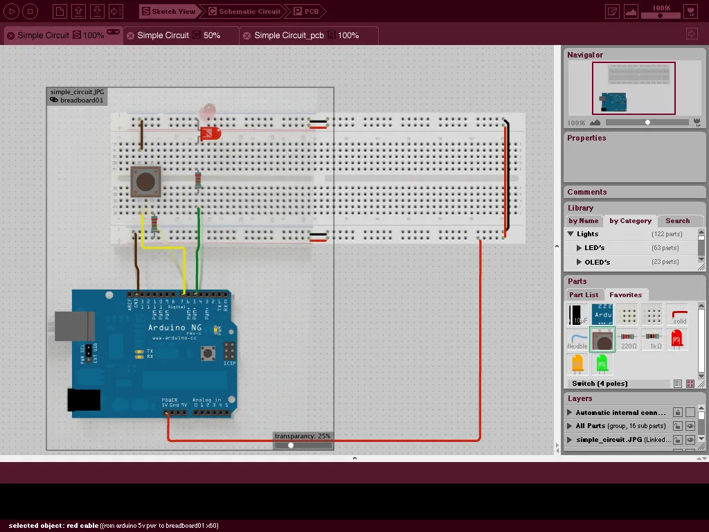
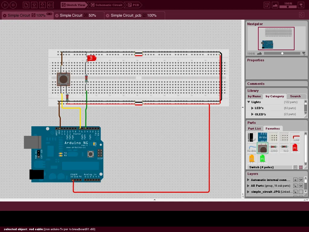
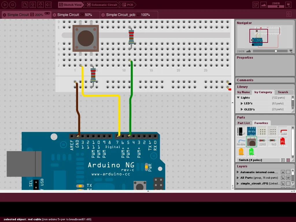
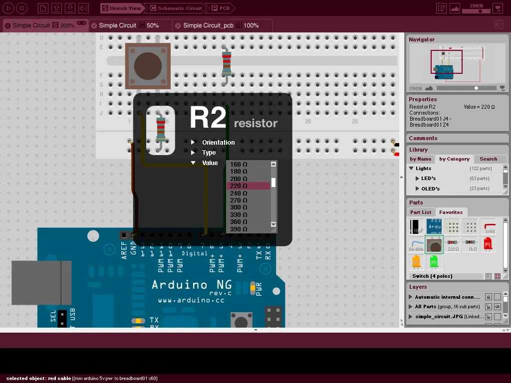
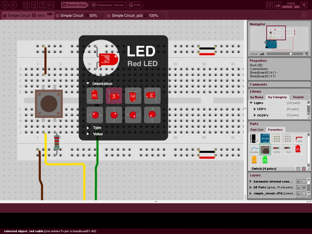
A sequence, made in a few days to convince the team to hire me, showing how a photo of a real breadboard can be imported, traced and introspected.
Toolbar iterations
A selection of the many toolbars we introduced and removed again over the project's life.




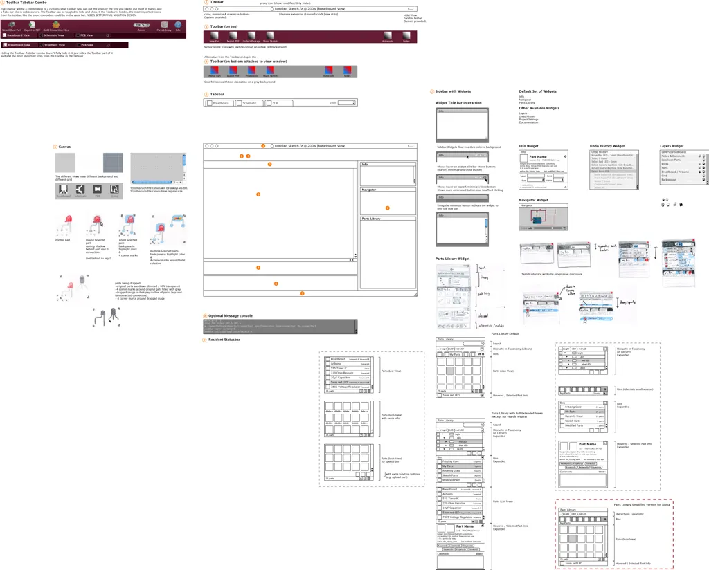
Wireframe
An early wireframe skeleton bringing the main interface elements together.
More